Articles

How to test air registers

In 1329, the industry of air registers was founded in Iran by Mr. Ahmad Shahrokhi. Considering the 60-year history of this industry in Iran and the variety of production in these products, there is no reliable reference for design engineers to use for calculations and control, and the engineers’ information is limited to tables in foreign catalogs or samples copied from them in domestic catalogs. Is.

This problem in Iran’s facilities industry was solved by establishing and setting up the first air register testing laboratory in Iran. Considering the importance of the issue and the fact that in the future, the first national standard mark of Iran in the industry of air registers will be issued in this laboratory by testing these registers, it was deemed necessary to provide a summary of the process and method of testing for the information of facility engineers.

The first laboratory for testing air regulating registers based on ISO 5221, ISO 5219 and national standard No. 7693 and 7695 was established with the advice of Amir Kabir University of Technology at the laboratory of Shahrokhi Industrial Factory and was approved by Iran Institute of Standards and Industrial Research.

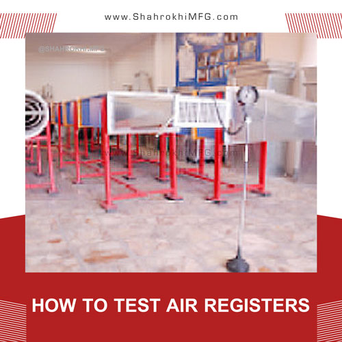
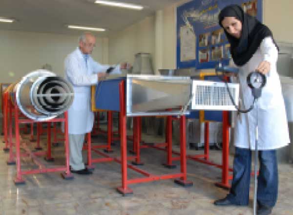
This laboratory is equipped with three air tunnels for round diffuser, square air flow and return air square, the length of which is designed according to the relevant standards. Inside the tunnels, the air flows gently using a 20 cm long honeycomb network and goes to the exit. The air flow is produced by a blower fan whose rotation is controlled by changing the frequency.
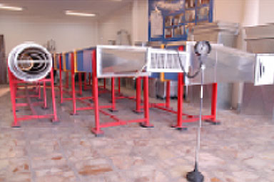
 

آزمایشگاه کارخانه صنعتی شاهرخی

Laboratory of Shahrokhi Industrial Factory

In this laboratory, things related to air flow speed, air flow rate, maximum speed in the entire register and register launch at the desired flow rate are measured. The obtained numbers are included in the product catalog and provided to engineers to use in their designs. So that if a air register is selected, the amount of drop, launch and aeration is known.
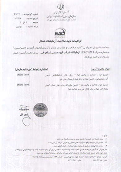
 

گواهینامه تایید صلاحیت آزمایشگاه شاهرخی

Certificate of qualification of Shahrokhi laboratory


First of all, we need to review the following definitions:

Static pressure SP: pressure on the channel walls.

Velocity pressure VP: pressure due to air movement in the channel.

Total pressure TP: Total air pressure, which is the sum of velocity pressure and static pressure.

Dynamic loss: with any change in the speed or direction of air movement along the channel (caused by the existence of coils, bends or changes in the dimensions of the channel), dynamic loss is created.

Measuring tools

    • Speed measuring device

The speed measuring device is a speedometer with an adjustable probe that has the ability to record the speed with an accuracy of 0.1. This device is digital and has a calibration certificate.

The probe can be placed in different positions, because the velocity gradient may be high at the measurement point or points, and the probe needs to be moved during the test.

  • Thermometer and barometer:

Air temperature affects the outputs of measuring devices. Because the measured air speed depends on the density, air temperature and actual air speed. Therefore, it is necessary to correct the obtained speed by measuring the temperature and air pressure.
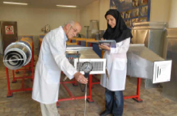


آزمایشگاه کارخانه صنعتی شاهرخی


  • Pitot tube:

The most common sensor tool for measuring velocity pressure is pitot tube. This device consists of two tubes, one inside the other. The tube enters the channel so that its tip is towards the air flow. The total pressure is sensed by the hole in the tube tip.

Static pressure is sensed by holes around the outside of the tube. Pitot tube has two outlets that measure pressure values. If the static pressure is subtracted from the total pressure, the remaining pressure is the velocity pressure.

  • Manometer:

A manometer is used as a display instrument, which is connected to the two outlets of the pitot tube. The manometer subtracts the total pressure and the static pressure and displays the velocity pressure at the outlet.


نحوه تست و آزمايش دريچه های تنظيم هوا

How to test air registers


How to test the register

At the beginning of the work, the register is connected to the channel with a suitable conversion. If the vanes of the register are adjustable, they are placed at zero degree and we turn on the blower fan. The auxiliary channel is connected in the next part of the air register.

At five points we measure the speed at the end of the channel. These five points in round registers, if D is the diameter of the valve, on a circle with radius R so that R=0.4D and in square valves with side lengths a and b on a rectangle with diameter length L=0.4√a2+b2 we choose.

We calculate the average of the five numbers obtained and consider it as the air flow speed. The product of the air flow speed in the cross section of the auxiliary channel is defined as the air flow rate.

At this stage, the auxiliary channel is separated, at a distance of 30 cm from the register, on a line parallel to the air register and passing through its central axis, we measure the air flow speed at consecutive points and at a distance of 5 cm from each other. Determine the point of the horizontal line that has the highest speed and pass a parallel line through it with a valve perpendicular to the previous line and measure the speed of the air flow in consecutive points at a distance of 5 cm from each other.

We determine a point of the vertical line that has the highest speed and consider this point as the maximum speed in the entire air register.

The speed measuring device is placed at this point and moved away from it in the direction perpendicular to the surface of the valve and the air flow speed is measured at successive intervals of 0.5 meters, this distance is measured until the air flow speed is 0.5 m/s. We will increase it. We define the distance from this point to the register as the air register throw at the desired flow rate. With the obtained information, you can draw the speed-launch diagram and use it for other speeds.

For air registers with other dimensions, the obtained numbers are developed using a linear equation. After finishing the design of the ventilation system, with the desired air volume and maximum register launch, we select its type and design and specify it in the calculation sheets. By doing this, the difference between design and implementation will be minimized.
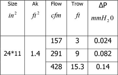
 

نمونه محاسبات برای دریچه دیواری دو طرفه

Calculation example for wall type registers with two way adjustable
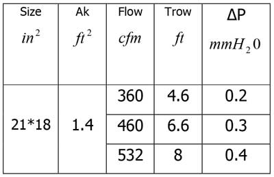
نمونه محاسبات برای دریچه سقفی دو طرفه

Calculation example for two-way ceiling diffuser
Shahrokhi Industrial Group

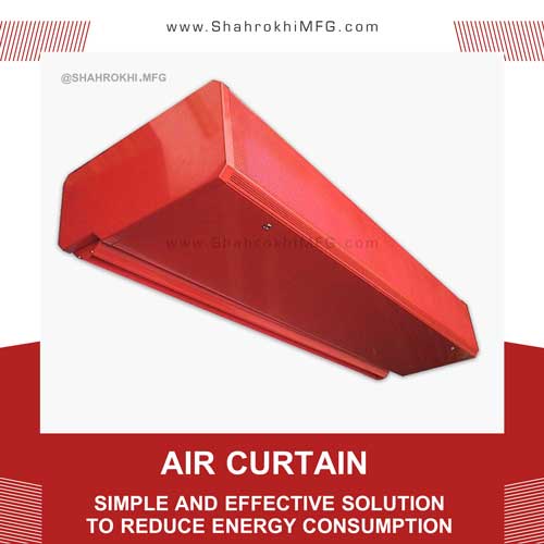
Air curtain simple and effective solution to reduce energy consumption

What is an air curtain?

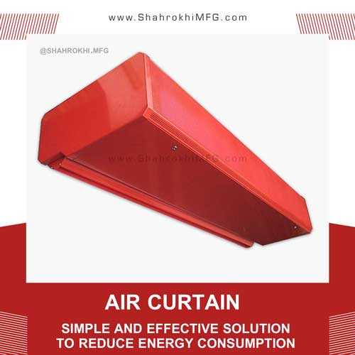
The air curtain is used as one of the air conditioning devices in buildings to reduce the dispersion of air flow through the traffic areas of the building and to improve the performance of other ventilation equipment.

Air curtain is a simple and effective solution to reduce energy consumption

Air curtain is a simple and effective solution to reduce energy consumption

The air curtain creates a surface of high velocity air that is thrown down the open door or across other open surfaces. Air flow is created by a number of fans that are usually installed on top of the door. The air curtain is also a very good barrier against the entry of insects, rain, wind, and dust from outside into the building.

The right choice of an air curtain can be a very good factor in reducing energy consumption and increasing the performance of air conditioning systems.

In this article, while introducing the air curtain, the performance of this device has been checked to determine the advantages of using it. Also, the most important main factors in designing a suitable air curtain are given.

How the air curtain works

The main parts of an air curtain are motor, fan, launch nozzle and controller, which have different power and dimensions according to the operating conditions. Air is sucked from the inside or outside of the building by fans, which can pass through the hot or cold coil. Then it comes out of the nozzle at a high speed and covers the open surface.

Generally, their dimensions are from 1 meter to 3 meters, which cover the height from 2.75 meters to 4 meters. The air speed in them is from 3.5 to 15.25 meters per second, which is produced by powerful engines of 0.48 to 4.7 kW.


زوایای پوشش پرده هوا

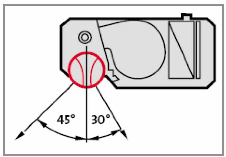
Air curtain cover angles

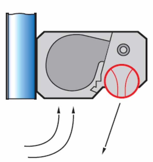
The thickness of the produced air curtain is from 2 to 5 inches, which is thrown towards the outlet at a suitable angle. The most suitable size of the launch angle is between 20 and 30 degrees. (opposite figure)


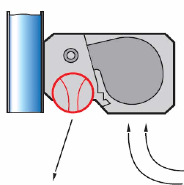
پرتاب هوا به سمت خارج و جلوگیری از تبادل انرژی

Blowing air out and preventing energy exchange

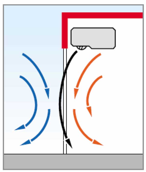
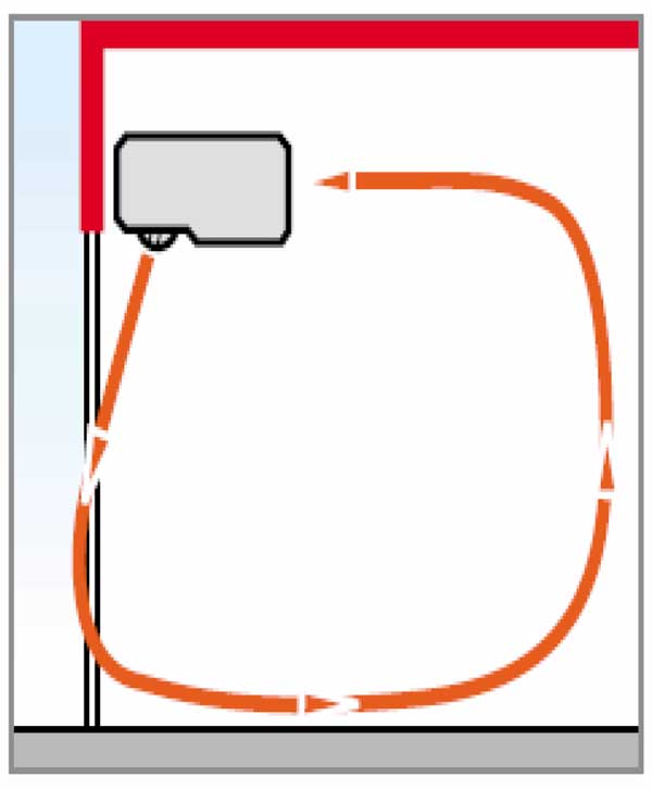
The air curtain makes the ventilation devices that are near the exit work better and reduces the heat and cold consumption in the building. This system reduces heat losses in the building by throwing warmer air from the higher level of the building.

Using a heating or cooling coil is not always economical due to the important energy consumption inside the coil, and in most applications, the same air inside or outside the design is used for launch. All of the above will eventually lead to a reduction in energy consumption. (opposite figure)


Types of air curtains

Today, air curtains are produced in various types with different functions

  • Air curtain with suction of heated air inside
  • With suction from the air inside
  • Compound with suction from inside air
  • With suction from outside air
  • For head rooms
  • For doors with high traffic


مکش از هوای تهویه شده داخل و پرتاب از نازل با زاویه به سمت خروجی

Suction of conditioned air inside and ejection from the nozzle at an angle towards the outlet

The first four rows of air curtains are installed at the exit of heated or cooled rooms that must be kept at a standard temperature. In all cases of this device, it is a uniform jet of air that is thrown at the right angle towards the open area. They are used for relatively small doors with dimensions up to 3.6 x 3.6 meters.

مکش از هوای خارج و پرتاب از نازل با زاویه به سمت خروجی

Suction from the outside air and ejection from the nozzle at an angle towards the outlet

Mixed air by throwing heated and unheated air at an angle of 15 degrees from each other reduces costs and rational use of energy. This type of air curtain preserves thermal energy by 25-60% and reduces costs by 30-70%, which depends on the dimensions of the door and the weather conditions of the area.

Air curtains for cold rooms are used in all kinds of cold rooms and rooms that are artificially cooled, such as vegetable and fruit storage areas, cold rooms, freezers, etc.

جلوگیری پرده هوا از تبادل انرژی بین دو محیط

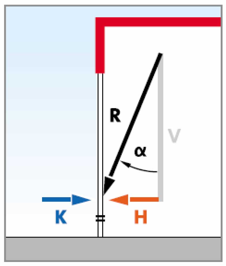
Preventing the air curtain from exchanging energy between two environments

The air curtain for high-traffic doors uses the feature of releasing free air with atomic pressure, 60% of the total cooling energy in a store is spent on ventilation, 80% of it is spent on overcoming the hot incoming air. Also, in factories and production halls that are not far from the office or other clean areas, using this system is a very good barrier to prevent the air from entering the hall into the clean area. The efficiency of this work is 70%.

حرکت هوای خارج شده از نازل در محیط

The movement of the air coming out of the nozzle in the environment

Among the other uses of the device, it is used in paint rooms to prevent paint from splashing into the outside environment or in furnaces, it prevents the waste of furnace heat, and as a result, reduces fuel consumption. The air curtain itself is considered an energy consumer, but this factor should be compared with its performance.

Air curtain effect

The effect of the air curtain in preventing energy wastage is 60 to 80 percent. This value will be evident by comparing two places where one is installed with an air curtain and the other is without an air curtain.

Lawton and Howell in 1995 performed a utility analysis on air curtains for different doors in hot and humid climates. Two factors of pressure changes in two environments and working height were influential in choosing the right air curtain.

Due to the very good performance of the air curtain in reducing energy consumption, its use has become mandatory in most developed countries. Also, calculations related to the design of a suitable air curtain are given in most ventilation books.


The main factors in air curtain design

The speed of air exit from the air curtain is calculated by the following equation:

فرمول محاسبه سرعت خروجی هوا از پرده هوا

The formula for calculating the speed of air exit from the air curtain

where V0 is the air outlet velocity in fpm

Δp is the average pressure difference between outside and inside air near the open air curtain door

ƒ The ratio of the air exiting from the air curtain to the door surface for the mixed air curtain with outside air is ƒ from 10 to 20 and for the normal air curtain from 20 to 40.

β0 is the homogeneity of the air exit along the nozzle of the air curtain and is from 1.05 to 1.1.

Ρ the density of the air blown by the air curtain

E dynamic coefficient of the air curtain, (table of dynamic coefficients of the air curtain)

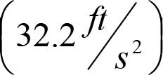
g acceleration | gravityشتاب جاذبه

The air flow coming out of the air curtain is obtained from the following equation:

G0 = pV0A0

We get the temperature of the blown air using the temperature balance equation. (table of m1 and m2 coefficients):

t0 = tout + m1(tmix – tout) + m2(toz – tout)

where Tmix is the temperature of the normal air mixture and m1, m2 are the air curtain coefficients obtained from the following table:


Table of dynamic air curtain coefficients

Table of m1 and m2 coefficients

Reference:

1- www.shahrokhimfg.com

2- “Development and Evaluation of an air-curtain fume cabinet with considerations of it’s aerodynamics.” R.F.Huang, Y.D.Wu, 2006

3- www.teddington.de

4- Fan Handbook: Selection, Application, and Design. By Frank P.Bleier.

5- ASHRAE HAND BOOK, Application

6- Industrial Ventilation Design Guide book. By Howard D.Goodfellow

Shahrokhi Industrial Group