How to test air registers
In 1329, the industry of air registers was founded in Iran by Mr. Ahmad Shahrokhi. Considering the 60-year history of this industry in Iran and the variety of production in these products, there is no reliable reference for design engineers to use for calculations and control, and the engineers’ information is limited to tables in foreign catalogs or samples copied from them in domestic catalogs. Is.
This problem in Iran’s facilities industry was solved by establishing and setting up the first air register testing laboratory in Iran. Considering the importance of the issue and the fact that in the future, the first national standard mark of Iran in the industry of air registers will be issued in this laboratory by testing these registers, it was deemed necessary to provide a summary of the process and method of testing for the information of facility engineers.
The first laboratory for testing air regulating registers based on ISO 5221, ISO 5219 and national standard No. 7693 and 7695 was established with the advice of Amir Kabir University of Technology at the laboratory of Shahrokhi Industrial Factory and was approved by Iran Institute of Standards and Industrial Research.
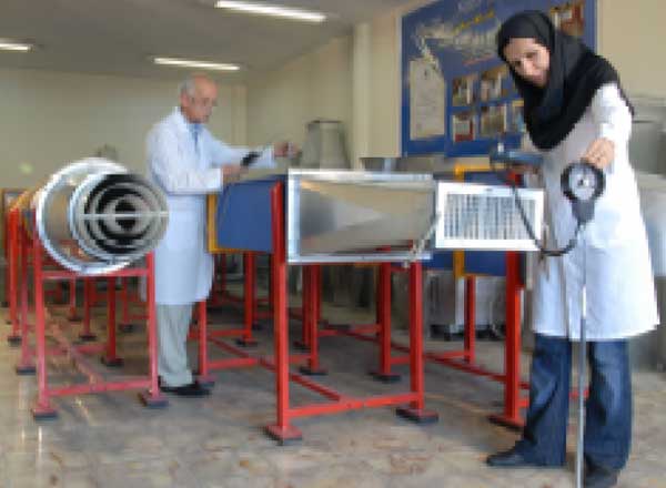
This laboratory is equipped with three air tunnels for round diffuser, square air flow and return air square, the length of which is designed according to the relevant standards. Inside the tunnels, the air flows gently using a 20 cm long honeycomb network and goes to the exit. The air flow is produced by a blower fan whose rotation is controlled by changing the frequency.
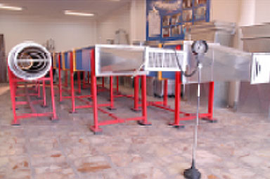
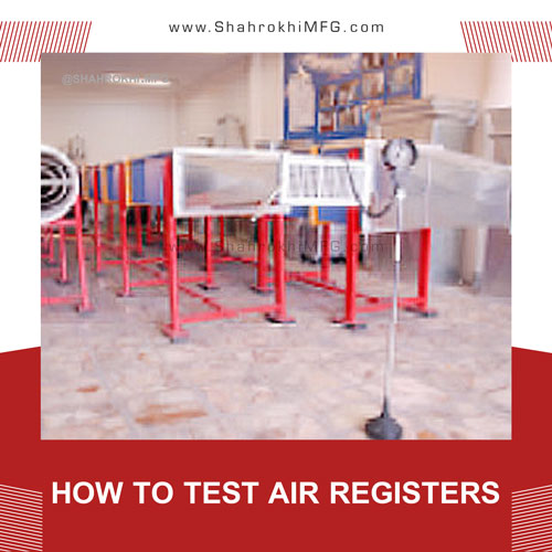
Laboratory of Shahrokhi Industrial Factory
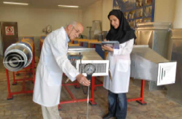
In this laboratory, things related to air flow speed, air flow rate, maximum speed in the entire register and register launch at the desired flow rate are measured. The obtained numbers are included in the product catalog and provided to engineers to use in their designs. So that if a air register is selected, the amount of drop, launch and aeration is known.
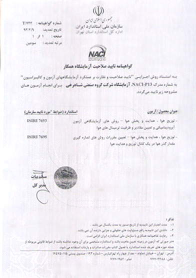
Certificate of qualification of Shahrokhi laboratory
First of all, we need to review the following definitions:
Static pressure SP: pressure on the channel walls.
Velocity pressure VP: pressure due to air movement in the channel.
Total pressure TP: Total air pressure, which is the sum of velocity pressure and static pressure.
Dynamic loss: with any change in the speed or direction of air movement along the channel (caused by the existence of coils, bends or changes in the dimensions of the channel), dynamic loss is created.
Measuring tools
-
-
Speed measuring device
-
The speed measuring device is a speedometer with an adjustable probe that has the ability to record the speed with an accuracy of 0.1. This device is digital and has a calibration certificate.
The probe can be placed in different positions, because the velocity gradient may be high at the measurement point or points, and the probe needs to be moved during the test.
-
Thermometer and barometer:
Air temperature affects the outputs of measuring devices. Because the measured air speed depends on the density, air temperature and actual air speed. Therefore, it is necessary to correct the obtained speed by measuring the temperature and air pressure.
-
Pitot tube:
The most common sensor tool for measuring velocity pressure is pitot tube. This device consists of two tubes, one inside the other. The tube enters the channel so that its tip is towards the air flow. The total pressure is sensed by the hole in the tube tip.
Static pressure is sensed by holes around the outside of the tube. Pitot tube has two outlets that measure pressure values. If the static pressure is subtracted from the total pressure, the remaining pressure is the velocity pressure.
-
Manometer:
A manometer is used as a display instrument, which is connected to the two outlets of the pitot tube. The manometer subtracts the total pressure and the static pressure and displays the velocity pressure at the outlet.
How to test air registers
How to test the register
At the beginning of the work, the register is connected to the channel with a suitable conversion. If the vanes of the register are adjustable, they are placed at zero degree and we turn on the blower fan. The auxiliary channel is connected in the next part of the air register.
At five points we measure the speed at the end of the channel. These five points in round registers, if D is the diameter of the valve, on a circle with radius R so that R=0.4D and in square valves with side lengths a and b on a rectangle with diameter length L=0.4√a2+b2 we choose.
We calculate the average of the five numbers obtained and consider it as the air flow speed. The product of the air flow speed in the cross section of the auxiliary channel is defined as the air flow rate.
At this stage, the auxiliary channel is separated, at a distance of 30 cm from the register, on a line parallel to the air register and passing through its central axis, we measure the air flow speed at consecutive points and at a distance of 5 cm from each other. Determine the point of the horizontal line that has the highest speed and pass a parallel line through it with a valve perpendicular to the previous line and measure the speed of the air flow in consecutive points at a distance of 5 cm from each other.
We determine a point of the vertical line that has the highest speed and consider this point as the maximum speed in the entire air register.
The speed measuring device is placed at this point and moved away from it in the direction perpendicular to the surface of the valve and the air flow speed is measured at successive intervals of 0.5 meters, this distance is measured until the air flow speed is 0.5 m/s. We will increase it. We define the distance from this point to the register as the air register throw at the desired flow rate. With the obtained information, you can draw the speed-launch diagram and use it for other speeds.
For air registers with other dimensions, the obtained numbers are developed using a linear equation. After finishing the design of the ventilation system, with the desired air volume and maximum register launch, we select its type and design and specify it in the calculation sheets. By doing this, the difference between design and implementation will be minimized.
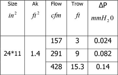
Calculation example for wall type registers with two way adjustable
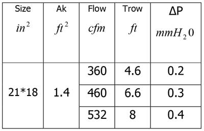
Calculation example for two-way ceiling diffuser


Leave a Reply
Want to join the discussion?Feel free to contribute!