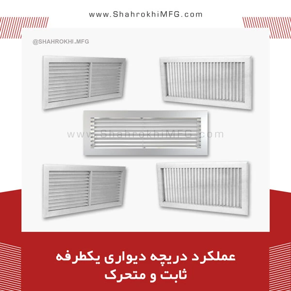
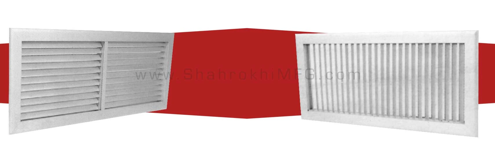
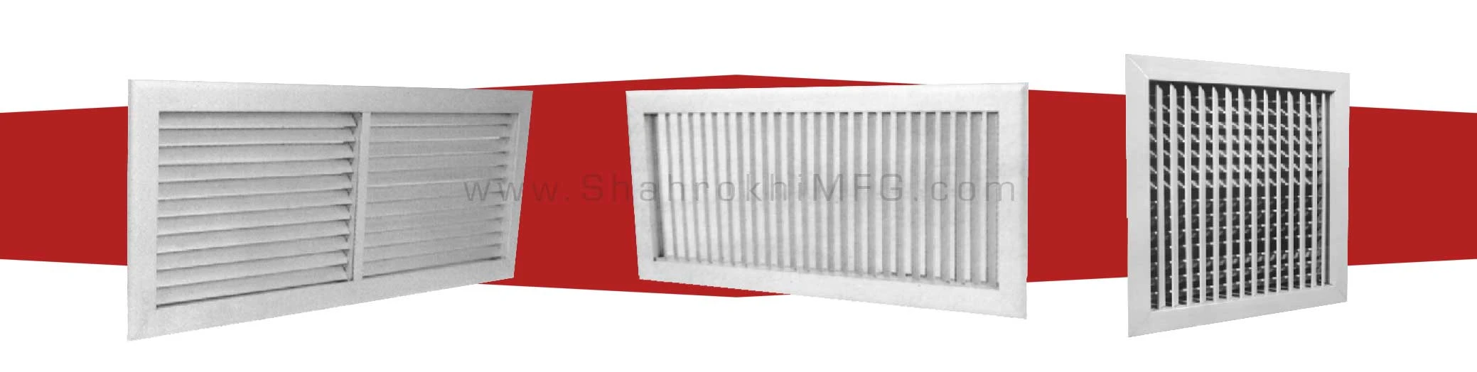
https://shahrokhimfg.com/wp-content/uploads/2023/12/amalkard-daricheh-yekt.webp600600alandhttps://shahrokhimfg.com/wp-content/uploads/2026/05/shahrokhi-logo-site.webpaland2023-12-11 00:54:432023-12-11 01:04:00wall type registers with one way adjustable blades function
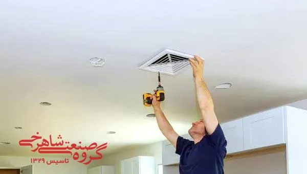
In the air conditioning system, a mistake in placing the air registers and not choosing the most suitable place to install the registers can cause many problems. problems such as energy loss, increasing energy costs, limiting the capacity of the ventilation system and many other things.
In this article, we are going to examine the most appropriate place to install air register and air return valves in the HVAC system and the problems related to not paying attention to these items.
Installation location of the air return register in the ventilation system
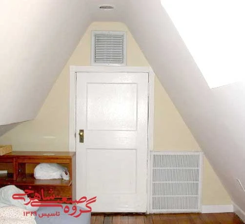
The presence of both air return and return valves in close proximity causes a competition for air supply and return. In this case, due to their proximity to each other, it leads to a short circuit between the two airs. For example, the register that directs the cold air into the room, if it is above the entrance door and the air return register is adjacent to it and lower, it causes the cold air to enter the room directly to the bottom of the room and the air return air register. to be transferred In this case, the air goes out quickly instead of circulating in the room.
HVAC experts call this air movement short-circuiting: supply air returns directly to the return duct instead of mixing with air in the cooled or heated space.
Poorly located vents and return air ducts like this can severely reduce the effectiveness of a cooling system and increase operating costs.
The location of the hot or cold air return air register in the basement and engine rooms
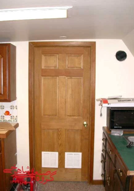
Placing the air register on the bottom of the door in basements and engine rooms is very common. This increases the operating costs of the heating or cooling system. In addition, the incorrect position of the valves in these places entails potential risks, including the risks of carbon monoxide emission.
Carbon Monoxide Hazards: Return air registers too close to oil or gas equipment may allow combustion gases or carbon monoxide into the air duct system, sending hazardous gases into the living space.
Be careful: You should not normally detect persistent CO in indoor air. Carbon monoxide gas indoors is odorless and colorless and can be deadly. Make sure your building has properly installed and working CO detectors and smoke detectors.
Installing ducts and heating or cooling systems on exterior walls
Heating or cooling return air duct systems that place the return air register in the exterior walls of the building may have poor performance.
Some engineers believe that efficient and cost-effective design and proper selection of valves on internal walls is more suitable and standard.
These were examples of improper use of register in inappropriate places that we discussed. The placement and selection of the most suitable valve is a matter that requires careful expertise. Shahrokhi Industrial Group, the first and largest manufacturer of air control air register in Iran, can help you in this matter. Contact our experts now for advice and expertise.
https://shahrokhimfg.com/wp-content/uploads/2023/11/best-location-1.webp500500alandhttps://shahrokhimfg.com/wp-content/uploads/2026/05/shahrokhi-logo-site.webpaland2023-11-15 17:11:112023-12-11 00:23:24Best location for air registers
All the products and services of Shahrokhi Industrial Group have a standard mark and ISO license, which shows the high quality of the products and their variety.
Shahrokhi company is also a member:
Iranian Facilities Industry Association
Association of Industry Quality Control Managers
Iranian Oil Industry Equipment Manufacturers Association
Road, Housing and Urban Development Research Center
Association of holders of standard badges of Iran
https://shahrokhimfg.com/wp-content/uploads/2023/11/shahrokhi-certs-en.webp800800alandhttps://shahrokhimfg.com/wp-content/uploads/2026/05/shahrokhi-logo-site.webpaland2023-11-01 17:40:122023-11-01 18:00:31Shahrokhi has the best marks of the Facilities industry in Iran
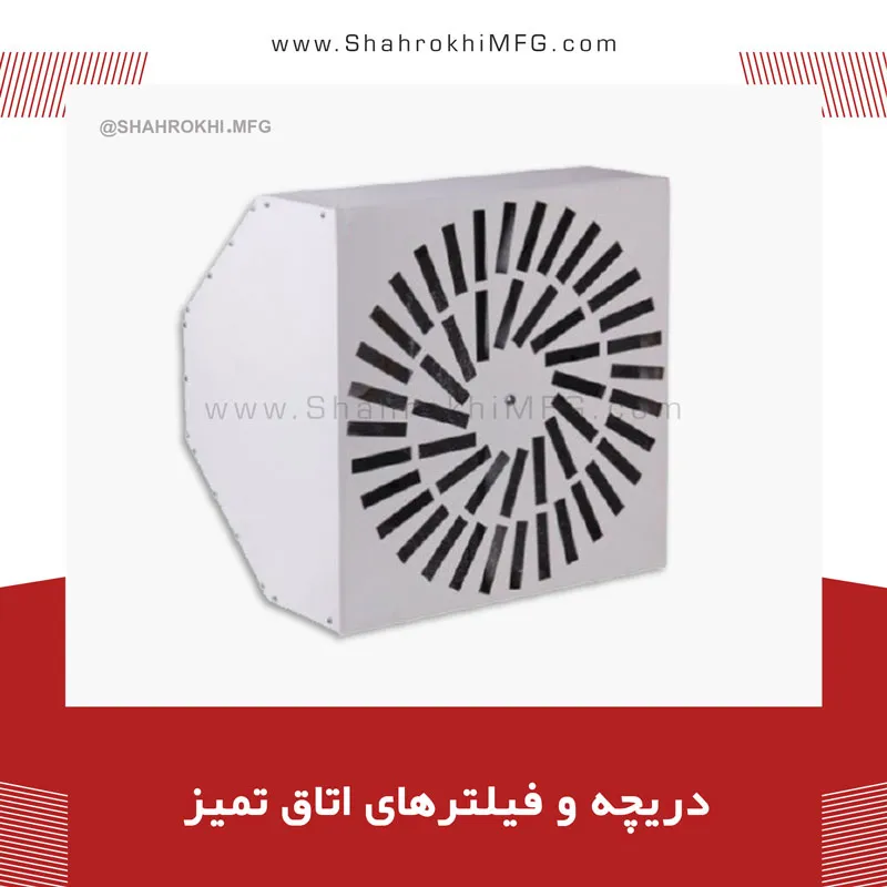
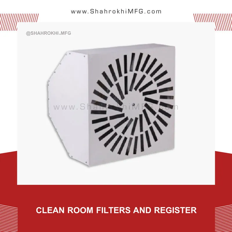
The main demand of the clean room industry is proper air conditioning and air quality. Air distribution in these rooms is done through solar vents with filters that are placed in filter holders (filter boxes), and in addition to that, to provide the required air and the number of times the air is changed into the rooms and the air is discharged from the inside. In a clean room, these types of valves are used to obtain the best physical parameters for circulating air..
Filter box
The main key to achieving clean air in clean rooms, such as drug production spaces, operating rooms, etc., is to choose the correct filtration method. Therefore, it is very important to choose a suitable filter and holder (filter box) that does not leak and does not reject the air flow without passing through the filter. Filter holders have 3 sections. Filter, filter box and air diffuser.
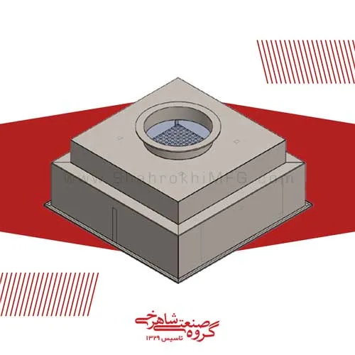
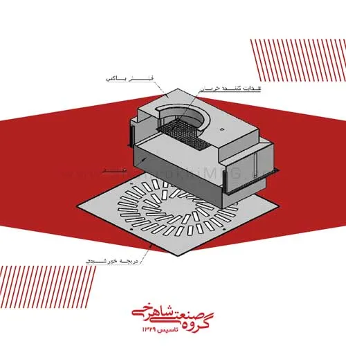
Figures 1 and 2 show a photo of the filter box from the front and back angles, and Figure 3 shows a disassembled filter box.
Figure 1- Front view of a sample filter box
Figure 2- The back view of a sample filter box
Figure 3- The disassembled filter box
Different plans and scenarios are adopted to reach different degrees of cleanliness, but ultimately the main element in each plan is the integration between the final filter and its filter box in the incoming air on the roof of the rooms.
The working process in the sanitary filter box is that at first the incoming air flow becomes completely uniform after passing through the flow equalizer and then it enters the sterile environment through the filter with the ability to absorb particles up to at least 95%. According to the design, the amount of particle absorption is determined by the filter). As a result, the air filter process continues at a very high level. These boxes are used in clean rooms that do not need heating and cooling systems.
Filter boxes can be used for recirculating air on the ceiling and wall.
solar valve
In some classifications of clean rooms, a common conventional method of a proper combination of clean incoming air with unclean air inside the room is used, which is based on the dilution of air in such a system.
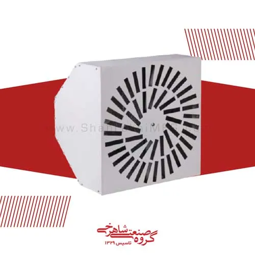
In order to have a perfect and diluted mixture in a clean room, the direction and speed of the incoming air flow is very important. The solar valves provide a suitable path for the incoming air at the entry point so that the required speed and direction are created for a perfect mixture.
The use of self-supporting blades, which were prepared by cutting and bending the surface of each valve itself, and creating a system of integration with the body of the valve, are a solution to have excellent air flow into the clean room.
The use of ABS air flow guide, which is produced by plastic injection process and installed on the air register, is a solution to have excellent air flow into the clean room. In addition, another advantage of these valves is the removal of unwanted parts of the existing older model valves, which has made cleaning the solar valves simple and easy.
The return air registers are also prepared simply so that by considering the speed on the surface of the valve and making accurate calculations to obtain the number and size of the bean holes on its surface, it is possible to gently move the air through the valves to prevent any noise. In order to keep the sound level inside the room as much as possible, extra is provided.
The size of the boxes and the partitioning conditions of the walls and ceiling in the clean rooms are such that after installation, the final level of the valve parts with the surface of the panels and other tools and accessories will be obtained completely.
Operating room air register
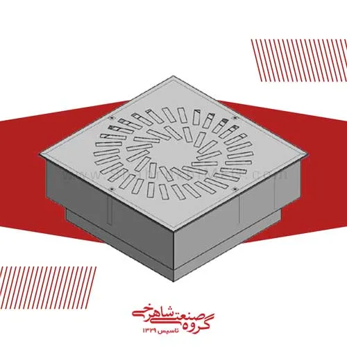
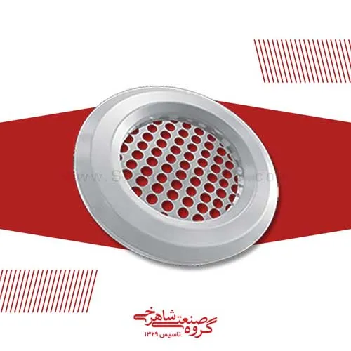
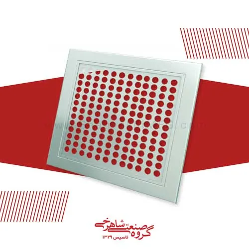
Operation room air registers are designed in two types, square roof and round roof with the ability to distribute air in a point for suitable applications in the air conditioning industry for use in hospital operating rooms or similar places. These valves are used for air intake and exhaust and distribute the air flow evenly. The operating room valves have a punched plate with 13 mm diameter holes that are easily installed on the channel. These valves have the ability to adjust the layers of air without any change in the volume, pressure and volume of the air.
In the air conditioning ducts, generally, due to the operation of the fan, whether axial fans or centrifugal fans, an unpleasant sound is dispersed in the environment. The intensity of this noise varies depending on factors such as the type of fan, the distance of the fan from the location, the type and type of channels and branches, the type of surrounding walls and other such factors, but in any case, the presence of this noise will create a disturbing environment for the residents.
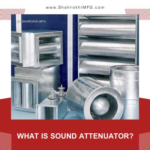
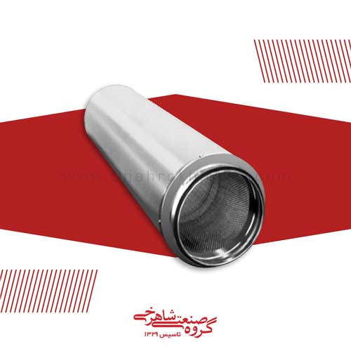
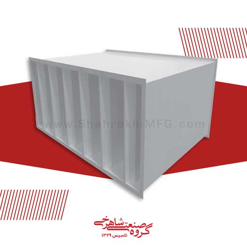
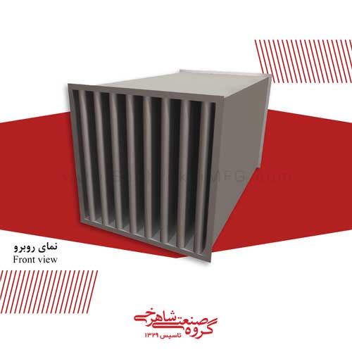
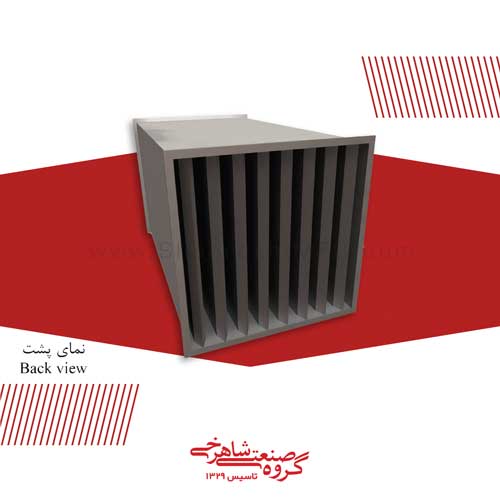
Nowadays, channel Sound Attenuator are used to solve this problem. With their special design, these Sound Attenuators, in addition to having the least impact on ventilation air flow, eliminate the sound produced by air conditioners to a great extent.
Silencers are widely used in industries such as metallurgy, electricity and power, mining and subway tunnels, and interior architecture in order to reduce HVAC system noise. The type and design of Sound Attenuator is such that it absorbs the noise produced with all kinds of frequencies and in the range of human hearing (from 63 Hz to 8000 Hz) it provides comfortable environmental conditions in terms of sound.
In this regard, the design of a suitable silencer that can provide these conditions in the environment is of special importance in such a way that in the case of improper design, the silencer will be able to absorb sound and as the cause of sound, it will double the problems. The basis of sound absorption in sound absorbers is based on the absorption of waves in porous materials.
Porous absorbent material
Sound absorbent materials absorb most of the sound energy and reflect a small amount of it. Therefore, the use of these materials is very useful to control the amount of noise, and they are used in various places such as points close to sources of noise production (such as fans in air conditioning systems) and inside air transmission channels.
There is a wide range of these materials that provide a variety of absorption properties based on sound frequency, composition type, thickness, outer surface, and installation method. Meanwhile, materials with high sound absorption coefficients are usually porous. A porous absorbent material is a solid that contains holes, channels, or slits that sound waves are able to enter.
Stone wool is among the family of thermal insulators consisting of mineral fibers. This insulation is a very desirable sound insulation due to the absence of sound transmission among the components and sound absorption, therefore, it is installed in airports, sound recording studios, under rails and in metro stations in cities. Increasing the thickness and creating a suitable air gap behind the insulation increases the amount of sound energy attenuation.
The geometry of Sound Attenuators
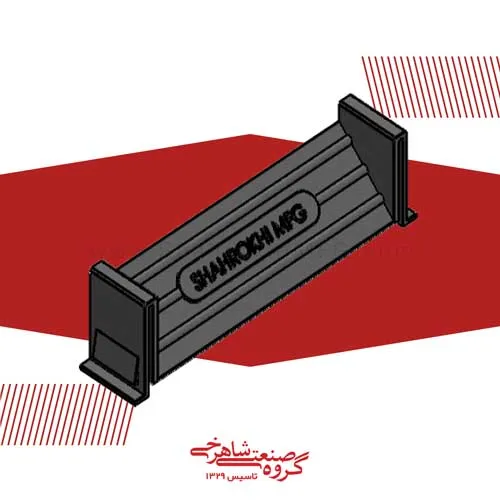
The structure of Sound Attenuators includes perforated sheets, where porous materials are placed between the two sheets depending on the place of use. Sound absorbers that are used in most cases today are in the form of vertical blades with specific length and width. Blades placed next to each other with equal distances in the ventilation channels.
Therefore, the passing air flow passing through these blades by means of two surfaces and the sound absorbing properties of the porous materials in the body of the blade, lose their accompanying sound to a certain extent. These Sound Attenuators have advantages, among which one can mention stability against air flow and wind speed, as well as the ability to replace damaged modules.
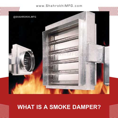
The smoke damper is used to prevent the passage of smoke and to prevent the passage of smoke and gases resulting from fire to another area in the way of air passage channels. When a fire occurs at a certain temperature, it closes automatically and prevents oxygen from reaching the fire and the spread of smoke to other areas.
Smoke dampers are divided into two main categories:
Fuse damper
Motorized damper
Fuse damper
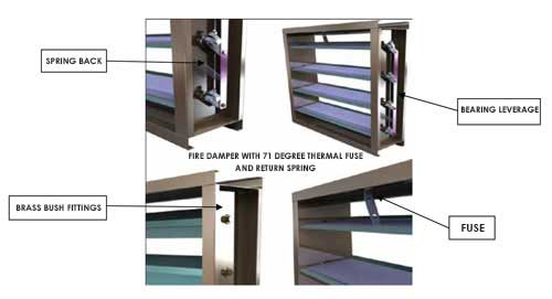
The main components used in these dampers usually consist of fuses, vanes with a tube inside them, and brass bush type connections. The fuses used in this type of dampers are divided into two general categories: solder and alcohol. Solder fuses work at 71 degrees and alcohol fuses at 68 and 79 degrees. These fuses are used in the role of the steering system to block the path of the air channel.
In the novel “The Origin of Fire”, the thermal element in the fuse of this type of damper melts at a certain temperature and leads to the closing of the damper blades and preventing the spread of fire.
Fuse damper
Motorized damper
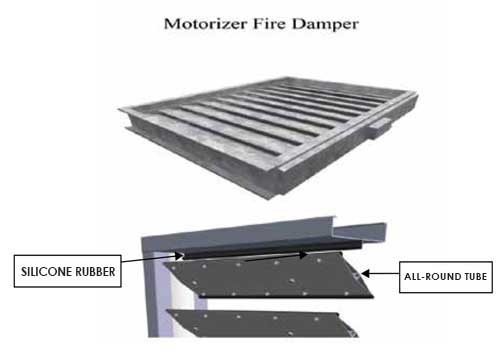
The components of this type of dampers are the same as fuse dampers, with the difference that the driving force of the vanes is provided by a motor and smoke and heat sensors are used instead of fuses. In places that have high safety, a special form of this type of damper is used, which consists of bearing levers, bearing connections, motor, double curtains, a tube inside the vane and heat-resistant silicone rubber.
These components can also be disassembled. Motorized dampers are closed using signals received from smoke and heat sensors located far from the damper.
Motorized damper
Smoke damper test
Two parameters have a significant effect on the performance of fire dampers:
The amount of leakage
Fire resistance level
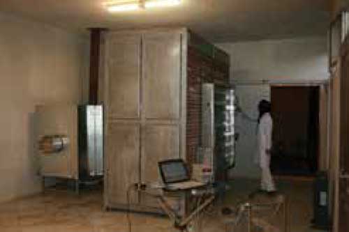
For this purpose, the fire damper must be subjected to two leakage and thermal tests for functional and resistance measurement, which will be described in the following process of performing these two tests.
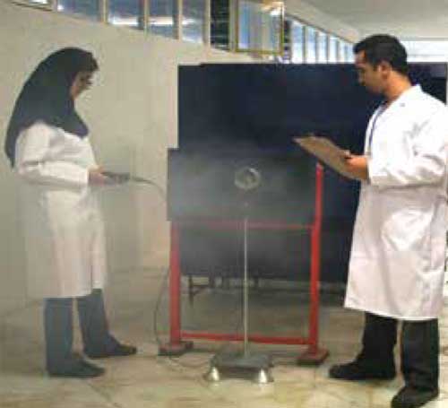
The purpose of this test is to determine the leakage rate of the smoke damper and its compliance with the relevant standard. The leakage test is performed in two times, before and after the thermal test. Among the written standards for leakage testing is the UL 555s standard.
In order to perform the leakage test, the damper is first closed on the channel and the damper is exposed to pressures of 250, 500, 1000, 2000 pascals in a completely closed state, and the volume of air coming out of the damper is measured.
Note: Smoke dampers manufactured by Shahrokhi Industrial Group have class 1 leakage with UL555S standard.
Leakage test
Thermal test of smoke damper
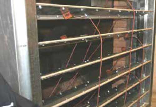
The purpose of this test is to determine the resistance of the damper against the heat resulting from the fire and to evaluate the behavior of a damper sample that is exposed to a certain heat and pressure. There are written and valid standards to perform this test, including EN12101-3 standards.
How to perform the test in order of steps is as follows:
– Damper leakage test according to AMCA Publication 500D standard
– Damper installation on the furnace
– Damper mechanical inspection
– The damper is closed and exposed to radiant heat.
– The temperature of the furnace has reached 250 degrees and the system must be designed in such a way that it can remain at a constant temperature of 250 degrees for 90 minutes.
– After the damper has been exposed to heat for 90 minutes, the damper opening and closing test is performed.
– Heading of the damper when the vanes are open at ambient temperature
– Damper mechanical inspection
– Damper leakage test according to AMCA Publication 500D standard
– Preparing the final report
A view of the damper being thermally tested
In this regard, Shahrokhi Industrial Group, since 2007, in order to manufacture, test and install smoke dampers for ongoing projects in its laboratory by purchasing new devices and calibrating them, making the necessary channels, making furnaces, providing fans with the ability Provide static pressure behind the damper (according to the customer’s request). Shahrokhi Industrial Group carried out all the mentioned measures under the supervision of the Standard Department and in cooperation with the German GL Inspection Company, and finally succeeded in obtaining the approval of the German GL Company to conduct the leakage and thermal testing of fireproof smoke dampers.
https://shahrokhimfg.com/wp-content/uploads/2023/02/What-is-a-smoke-damper.jpg500500alandhttps://shahrokhimfg.com/wp-content/uploads/2026/05/shahrokhi-logo-site.webpaland2022-11-05 11:31:402023-02-27 16:07:15What is a smoke damper
Air distribution – Shahrokhi air distribution system
Introduction
The conditions of the human environment have a direct effect on his mental states, physical condition, the way of doing work and in general all aspects of his life. Since the majority of human life today is spent inside the building, it is important to create favorable environmental conditions in the building, whether it is a workplace or a home, etc., the most important part of which is providing comfortable air for the residents of the building according to their type of activity.
In fact, the purpose of planning, calculating and installing the HVAC system is to create pleasant air for the residents according to their type of activity in the building, and the correct distribution of air in the rooms is the last step to achieve this goal, which plays a decisive role in creating comfortable conditions for the residents. Will have.
Air distribution
The transfer of a certain air flow, generally through the channel to the space or from the space(s) used, is called air distribution. Along the duct may be placed devices for the purpose of changing the conditions of the air (for example, purification, heating, cooling, humidification or dehumidification, etc.), which are called air conditioning devices, which are not discussed here.
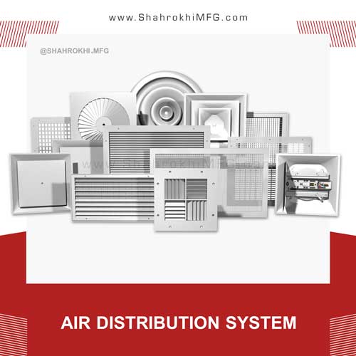
Air distribution in the room may be done through ceiling diffusers or wall registers. Before introducing the types of air distribution registers, the principles of air distribution are discussed briefly.
Air distribution in the operation space is carried out by air distribution devices, which are called air terminals, in such a way that predetermined conditions, such as the amount of air volume change, pressure, filtration, temperature, humidity, air speed, and sound level in an area to fulfill a certain requirement in this space, which is called the performance area. Air terminals are the common boundary between the operation space and the air distribution system.
Air distribution has principles, among which the following can be mentioned:
Room temperature: The air distribution in the room should be proportional so that the temperature changes in different parts of the room do not exceed a certain limit.
Primary and secondary air: The primary air is the amount of air that enters the room directly through the register, and the secondary air is the volume of air in the room that is displaced by the primary air and participates in the air circulation with it.
Air flow speed in the room: The best air movement speed for the occupants of the room is 50 feet per minute, especially when they are sitting. For buildings such as stores and factories where people are moving slowly, this speed can be increased to 150 feet per minute. Speeds higher than the permissible limit cause discomfort when the air hits the face or body of the residents.
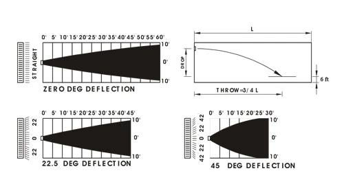
Air throw length: It is the horizontal distance that the air flow travels with respect to the air inlet register in the room. This distance is measured from the location of the air inlet to the point where the speed of the air flow reaches a certain minimum. This speed is at least 50 feet per minute.
Direction of air flow: This issue is also involved in creating comfortable conditions for residents.
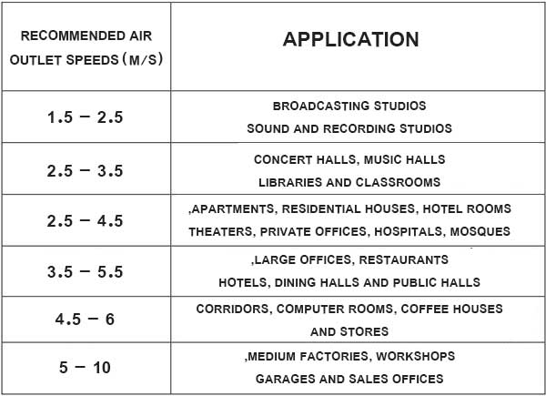
The speed of the air exiting the register: this speed should be determined according to the sound limit in the room. Suggested speeds for air exit from the register are listed in Table 1. It is necessary to explain that these speeds are determined based on the useful surface of the register, and the useful surface of the register is the product of the dimensions of the register minus the surfaces of the register blades.
Recommended air outlet speeds
The following are the main components of the air distribution system, and if necessary, these definitions are chosen according to the direction of the air flow inside the channel:
Air flow equalizers:
These components are used in order to make the speed uniform in the cross section of the flow, or to reduce the relative amount of flow disturbances, or to reduce the amount of possible rotation of the air flow.
Current balancers include:
Directional blades that are used in certain parts of the channel to reduce flow disturbances.
Straightening components in the form of squares or honeycombs, which are used in order to eliminate the possible rotation of the air flow.
Mesh plates, nets or similar components are used to even out the velocity distribution by increasing the pressure drop.
Dampers:
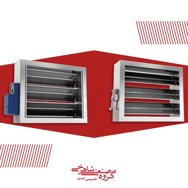
These devices can be used inside the air channels or together with the air terminals, in which case they are able to correct the air resistance of the system and thus change the passing air flow rate or control the air flow and in addition, if necessary, cut off the air flow.
Two examples of manual and motorized channel dampers
Types of air distribution registers
In order to better distribute the air in the room or space to be ventilated, a distribution register is used.
Next, two examples of these registers (double-sided wall register and square ceiling diffusers) will be described.
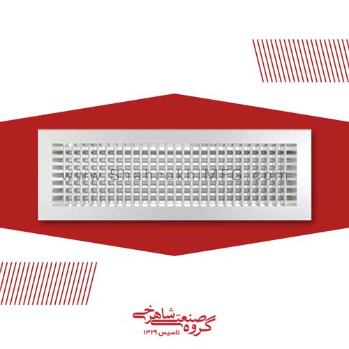
Two-way wall register
The two-way wall register with two rows of adjustable vanes has a number of horizontal and vertical parallel vanes that can be moved at any angle around its central axis. These registers are usually used for exhaust air. Horizontal and vertical blades can move at any angle.
Two-way wall register
The air regulation vanes, which are placed together parallel to the suitable cross-section for air passage, make it possible for the air flow to pass uniformly, with calmness and low pressure drop.
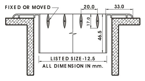
It is possible for the vanes to be fixed at an angle selectively during the manufacturing process, which is called the fixed type, and it is also possible that these vanes can be manually adjusted to any angle, which is called the movable type.
Plastic bushings or linear springs are used to separate the spokes from the frame in order to eliminate noise, and thus, the spokes are under tension during adjustment.
Several types of frames are available upon request, and the choice of frame type depends on the installation location of the registers.
Blades and frame are made of 1.25 mm thick aluminum profile with an anodized aluminum coating of good quality.
It is possible to use iron instead of aluminum upon request, and it is also possible to do the final painting by spraying liquid or powder paint (electrostatic).
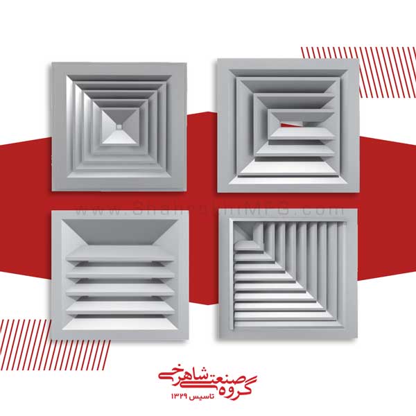
Square ceiling diffusers
Square ceiling diffusers are designed to be installed in the ceiling for suitable applications in the air conditioning industry. These registers are used for air flow, return and discharge, which spread uniform air flow horizontally by successive concentric vanes. These blades have the ability to distribute air in one to four directions.
One-way, two-way, three-way and four-way ceiling diffusers
These types of registers are easily installed on the square channel or by a conversion on the round channel. In these types of registers, the high amount of air distribution in the space under the roof makes the temperature and velocity of the mixed air quickly balance.
There are several types of frames for this type of register, the choice of which depends on the installation location of the registers. In some of these frames, it is possible for the internal blades to come out of the frame to install the register, adjust the damper, and wash. It is also possible to adjust the damper by creating a hole in the inner blades.
Frames and spokes are made of 1.25 mm thick aluminum profile with an anodized aluminum coating of good quality. It is possible that the final coloring can be done by spraying liquid or powder paint (electrostatic).
https://shahrokhimfg.com/wp-content/uploads/2023/02/air-distribution.jpg500500alandhttps://shahrokhimfg.com/wp-content/uploads/2026/05/shahrokhi-logo-site.webpaland2022-10-29 12:00:182023-02-27 17:40:19air distribution
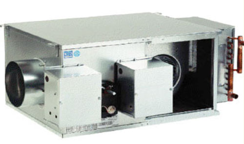
In this category of fan coils, by fully insulating the fan coil and also choosing the right fan and reducing the internal pressure drop, the sound caused by the fan is taken and thus the transmission of the fan sound to the environment is prevented.
This system can be used in environments with less thermal and cooling load and the need to limit the sound of the ventilation system, such as luxury places such as hotels, luxury conference halls and similar places.
The air in this system is supplied by the air generator, which has already been sounded.
VAV coil
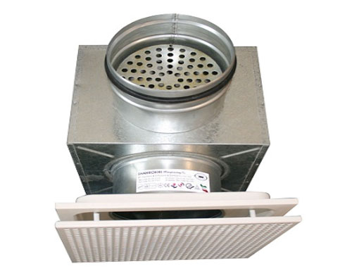
Plenum boxes and modern air registers
A ventilation system must produce and distribute a certain volume of air to create favorable air conditions. On the other hand, parameters such as the amount of sound production, air speed and temperature in the room should also be considered. For this purpose, in the design and selection of the air distribution system in each room, the appropriate type of air register, the shape and speed of the air projectile at different temperatures should be calculated and considered in the design in order to create the desired conditions.
Today, different types of modern air registers such as induction, solar and low impulse registers – all equipped with plenum boxes – can be used with very low noise level, about 25-35 db(A), while the air registers that are used in Iran today for Hitting the right projectile often produces a high sound level of around 40-50 db(A).
Plenum boxes and modern air registers
Plenum boxes and modern air registers
Plenum boxes
There are different methods for transferring air from the channel to the registers, which can be changed depending on the design conditions and installation restrictions.
One of the prominent systems in this regard is the use of plenum boxes. Today, this system is widely used in modern ventilation due to its special advantages and capabilities.
Advantages of plenum boxes
Very high volume, especially in low frequencies
Smoothing the air flow before reaching the valve at low altitude
The possibility of using a damper to adjust the air
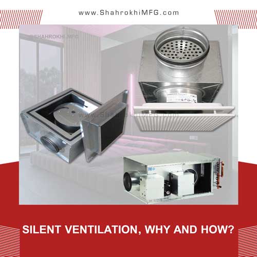
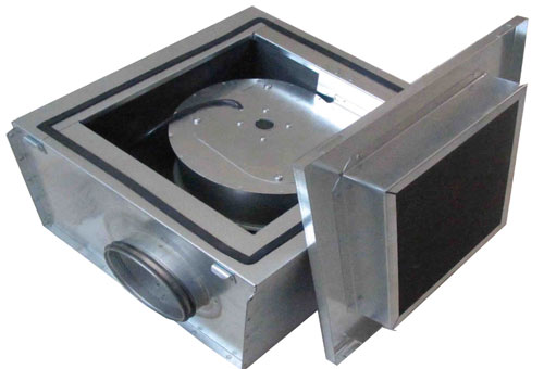
Sound Attenuator box fans
Nowadays, the role of insulated box fans in ventilation systems has become more and more colorful. It is very common to use this type of insulated fans – for example, in home ventilation systems.
Sound Attenuator box fans
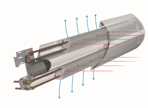
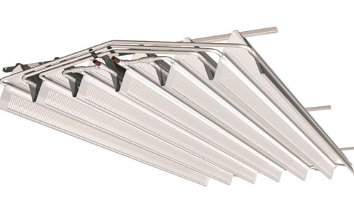
Childbeams
The use of strong induction property in the example of active childbeams has caused the complete elimination of the fan compared to the fan coils, which causes the complete elimination of sound.
About 20% of the incoming air in these systems is supplied by the air conditioner, which is already sound-proofed, and the remaining 80% enters the Childbeam from the environment by the induction property (suction) produced by the Childbeam.
Another type of child beam is its Passive type (that is, cooling ceiling panels), which are used to cool the ceiling.
Childbeams
The simultaneous use of radiation properties has a significant effect on the significant increase in the working efficiency of child beams, especially its passive type. In this type of child beam, without the intervention of a fan, the hot air goes up by the natural convection current and after hitting the coil and cooling, it moves down freely without the help of a fan and cools the ambient air.
In each passive and active Childbeam cooling unit, the water temperature between 15 and 17 degrees Celsius is pumped to the Childbeam by the water system in order to bring the ambient air temperature to the appropriate level.
The temperature of hot water in Active Childbeam type is around 50 degrees Celsius, which makes it possible to use solar energy for heating in winter.
Application level of this equipment
In the end, it is important to mention that all the equipment mentioned in this article have been used for many years as complementary components of the ventilation system in developed countries on a large scale. For example, the newest example of this equipment, namely Child Beams, entered the market more than fifteen years ago and today they are widely used in various types of ventilation systems, especially in European countries.
The conditions of the human environment have a direct effect on his mental states, physical condition, the way he does work and in general all aspects of his life. Since the majority of human life today is spent inside the building, creating favorable environmental conditions in the building, whether it is a workplace or a home, etc., is very important, the most important part of which is air conditioning for the residents of the building according to their type of activity.
The most beautiful and expensive buildings will not be habitable if they do not have proper air conditioning system.
Controlling temperature, humidity and air speed, removing dust and other air pollution, and if necessary, eliminating microbes and bacteria suspended in the air, heating and cooling the air according to the season, are the main tasks of an air conditioning system, and other Duties are next in importance.
Air conditioning (cooling – heating)
Systems and applications
Choosing the right type of air conditioning system for a particular space or building is a very sensitive decision.
The main issues that should be considered by the designer of the air conditioning system are:
1- Personal financial facilities or investor organization
2- Space or building (purpose, location)
3- Exterior characteristics of the building, temperature, humidity, wind, radiation, sun, shade
4- Changes in heat load inside the building (residents, lights)
5- The ability of the building to store the acquired heat
6- Necessity and capacity of pre-cooling to reduce the size of air conditioners or partial cooling of the building
7- The physical aspects of the space or building in terms of adapting to the air conditioning system of the equipment and adjusting the system performance, under partial heat load
8- The expectations of the employer’s personal statements about the quality of the ambient air
Applications of air conditioning
Although in theory any air conditioning system can be used for any building, but in practice due to the existence of factors such as investment and operation costs, space and location limitations, the architectural plan of the local building location and the evaluation and experience of the designer’s engineering. The number of suitable air conditioning systems for each building will be limited. Usually, in buildings whose heating and ventilation systems are simple and of adequate capacity, operation and maintenance costs will be relatively low.
Air conditioning applications are usually in public and commercial buildings (office buildings, libraries, transportation centers), assembly buildings (amphitheaters, studios), educational buildings (kindergartens, universities, schools), residential buildings (dormitories, hotels), residential buildings (single-unit, multi-unit, apartment), health and treatment centers (hospitals), etc., which we deal with the type of systems in residential buildings.
The type of air conditioning systems of residential buildings is affected by local and practical factors.
Available sources of energy and their price, weather conditions, social and economic characteristics and access to expert staff for installation and repairs are local factors and the type of building, technical characteristics of the building and regulations and standards of residential buildings are practical factors.
Therefore, various systems can be used for heating, cooling, humidification, humidification and air purification or combining these processes. Usually, residential buildings need cooling and heating; In many systems, they also perform air purification by adding conventional or electrostatic filters. In many systems, women’s humidity can also be used; Especially in the heating season and when it is necessary to increase the air humidity according to the psychometric conditions.
Common heating systems
Common heating systems for residential buildings consist of three main groups:
Forced air supply from the central station (central forced air), central water systems (Central hydronic) and regional systems (zonal) that select and design the system according to the type of energy source, how to distribute and transfer the medium of cooling and heating, terminal or consumer devices.
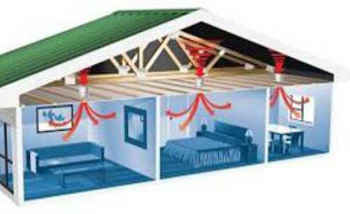
An incinerator consists of a two-piece air conditioning unit, humidity and air. The way the system works is that the air returns to the device through the return air channel, and in winter, the air circulation fan, which is a part of the furnace, feeds the heat to the desired space.
A humidifier adds the required moisture to the warm air that is distributed inside the building through ducts. During the cooling season, as the circulating air passes over the evaporator coil, heat and moisture are removed from the air and are the refrigerant pipe located outside is connected.
The moisture distilled on the surface of the evaporator coil is discharged through the discharge tube. Cooling and heating equipment in houses that are built as single-unit complexes or multi-story apartments are usually similar to single-unit buildings. Using a separate system for each unit allows each unit to be controlled independently. The amount of energy consumed by each unit can be measured.
Central system with forced air flow
In high-rise multi-unit buildings, the cooling equipment used in single-unit buildings can also be used. These equipment can be installed inside the equipment room of any apartment or in the space under the stairs or above the false ceiling or warehouse. Small hot air furnaces suitable for residential buildings can also be used, but the necessary provisions must be made to supply combustion air and discharge combustion products to Action will come.
Central system with forced air flow
For evacuation, several chimneys or a manifold type vent system can be used, although local regulations should be considered in this case.
Another method that can be used for multi-unit buildings is the combined water heating/space heating system, in which the water in the hot water storage tank is used for space heating. In this system, water from the storage tank to the coil; The water in the air feeding device circulates.
To cool these spaces, you can use a split system air conditioner whose evaporator is inside the air handler.
At this stage, the designer should think about the best ways to save energy in buildings, the steps and solutions for which are given in the winter magazine.
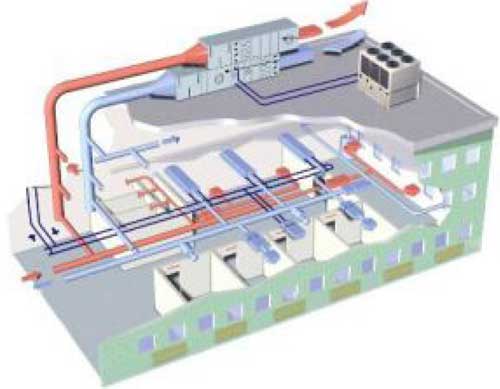
The main purpose of any HVAC system is to provide comfort. Comfort in a place depends on the combination of temperature and humidity. The HVAC system requires a certain amount of supply air to provide a significant combination of humidity and temperature within the comfort zone. About 60 to 70 percent of the energy consumed by buildings is used for ventilation and exchange of building air with the outside environment.
Therefore, one of the most appropriate ways to optimize energy consumption in buildings is the use of VAV systems.
VAV stands for “Variable Air Volume”. VAV is a ventilation control method and is used in buildings where the thermal or ventilation load is always variable. As the number of people in a room changes, the air quality (temperature, humidity, carbon dioxide) also changes, and this is done by placing an air quality measurement sensor such as CO2, temperature or humidity… which are good indicators of air quality. are adjusted.
Also, when heat sources such as the number of people, computers, and sunlight cause the heat load of the room to increase, it is necessary to cool or heat the room with an air conditioning system.
These things are always changing during the day and night and must be controlled by the ventilation system. By implementing the VAV system, temperature control conditions with variable air volume are provided.
Today, VAV systems can provide changes in the cooling and heating load required by the building. For this purpose, in VAV systems, a fan with variable speed is needed, which saves energy and cost to a great extent by reducing the power of the fan. The VAV system controls different loads in the rooms by opening and closing the air damper inside the mixing chamber.
VAV systems are divided into two categories:
Pressure dependent systems
Pressure independent systems
Pressure dependent systems:
In these systems, a motor damper is placed on the air damper entering each space, which controls the closing rate of the damper according to the temperature inside the room and the command received from the room thermostat.
Since the closing or opening of each damper affects the amount of static pressure in the duct and will cause a change in the amount of air passing through other dampers, therefore, this method depends on the static pressure inside the duct.
Pressure independent systems:
In this method, a VAV box is placed in each area, which is connected to the air distribution channels. The VAV box can adjust the volume of air entering the space or room according to the volume of passing air.
The temperature of the air outlet of the air conditioner is controlled and adjusted to a certain level. This certain amount of temperature is not constant and it is optimized by monitoring control and its set point is reset.
In the pressure independent VAV system, the volume of air entering the spaces changes to compensate for the cooling load based on the command received from the room unit.
In parallel and in accordance with the change in the volume of air poured into the room, the volume of air coming out of the air conditioner fan should also be adjusted.
It should be noted that in the VAV system, the opening or closing of the dampers is independent of the pressure, and it is the amount of air entering the rooms that is controlled.
Comparison of CAV system with VAV system
CAV system works based on variable temperature with constant air volume, but VAV system works at constant temperature with variable air volume.
In the CAV system, all the equipment works at maximum capacity, but in the VAV system, the equipment works based on the need.
Depreciation of devices in VAV system is lower than CAV system.
Sound pollution (noise) resulting from fan operation in VAV system is less than CAV system.
The possibility of temperature control in VAV system is more than CAV system.
Humidity control is not possible in the CAV system, but it is done in the VAV system.
The amount of energy consumption in the CAV system is much higher than the VAV system.
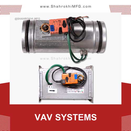
VAV Systems
General information:
Suitable for office, commercial, residential and laboratory applications
Suitable for controlling air volume, room or channel pressure
High control precision
Suitable for air velocity between 2 and 10 m/s
Advantages of the system: VAV
Ability to control temperature and humidity
Reducing the depreciation of related equipment such as fans and compressors
Reducing fan energy consumption
Creating less noise in the system
Return of the initial cost in a short period of time
VAV Systems
Types of VAVs manufactured by Shahrokhi Industrial Group:
Rectangular or square VAV box damper
Circular box VAV damper
VAV box damper with acoustic body (rectangular, circular)
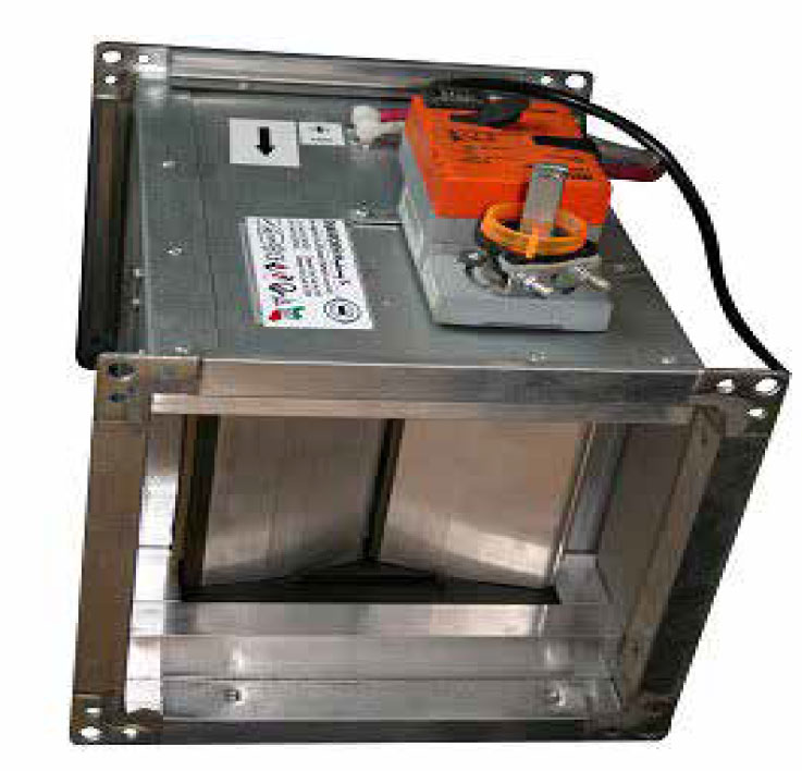
Rectangular damper components: VAV
Body with galvanized steel sheet
Opposite air foil model aluminum blades
Aluminum probes for measuring the pressure difference on both sides of the flange
Power transmission system for the movement of the blades, a gear model made of ABS plastic
Galvanized steel shaft
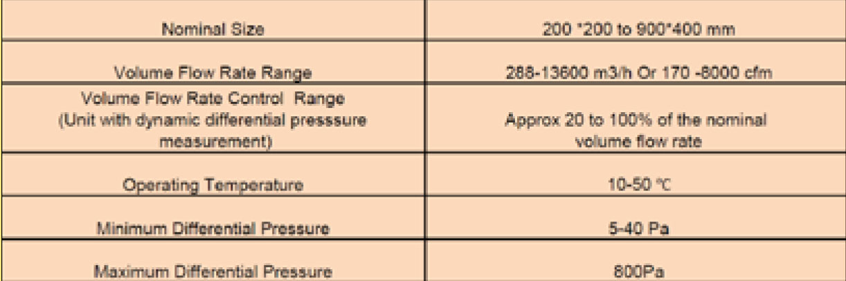
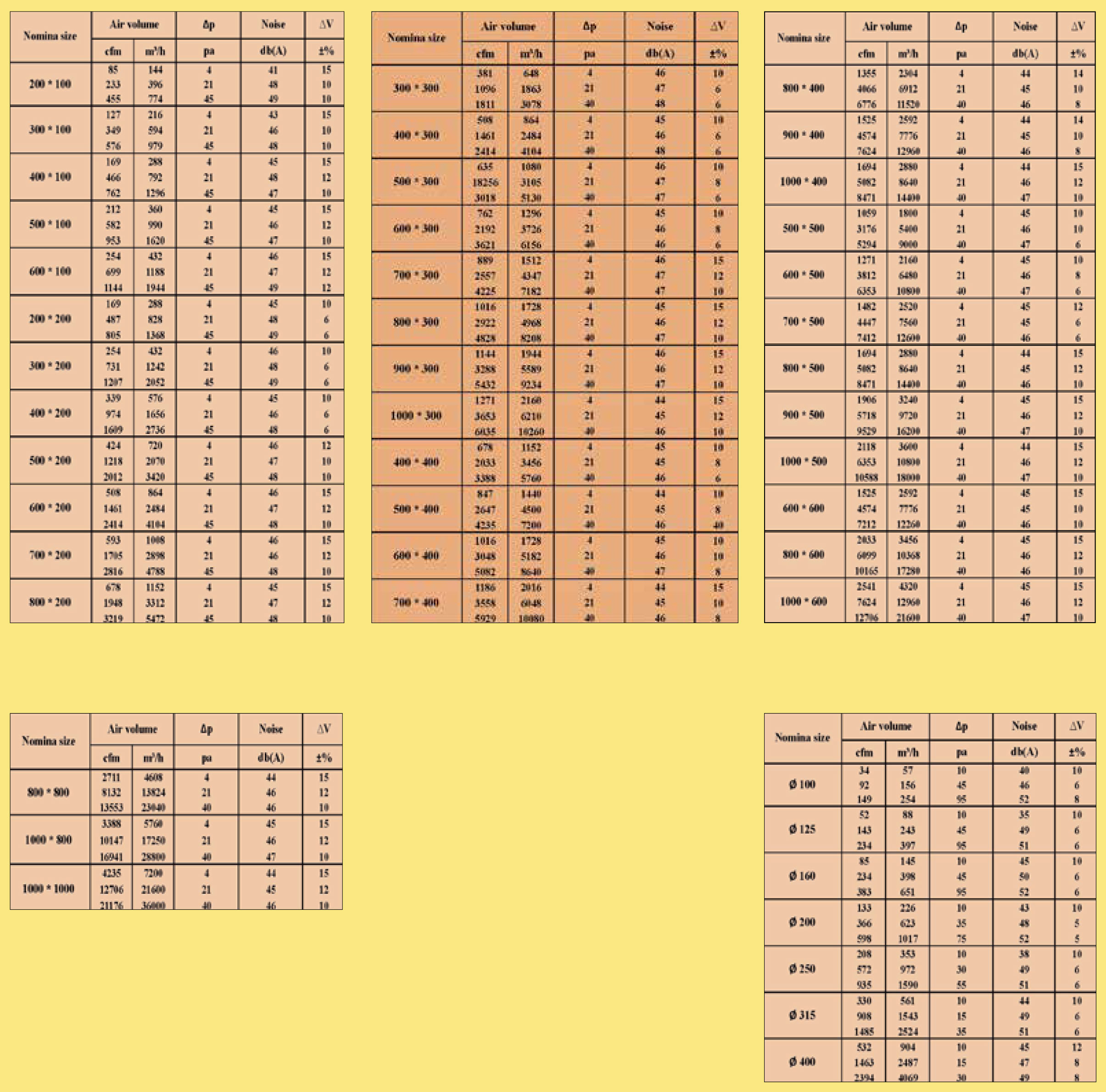
Rectangular VAV technical specifications
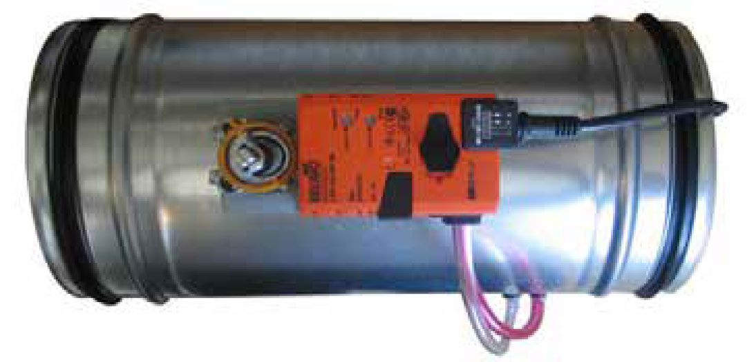
Circular damper components: VAV
Body with galvanized steel sheet
Single blade galvanized blade
Galvanized pressure measurement probes
Has air-tight rubber on both sides of the damper
Without flange (it is possible to install flanges on both sides)
Galvanized steel shaft
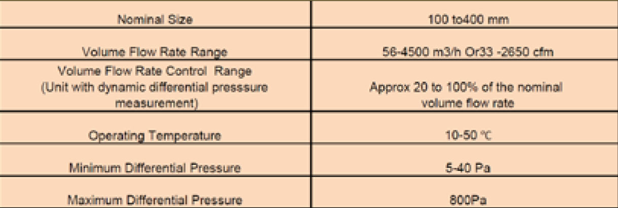
Technical specifications of round VAV
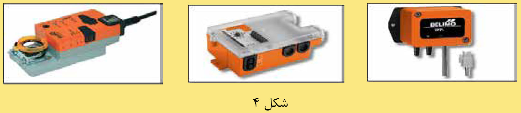
Damper control components: VAV
PC-Tool software program for functional tests of air flow controller system
Universal controller consisting of separate pressure difference sensor, separate controller and separate actuator for special applications
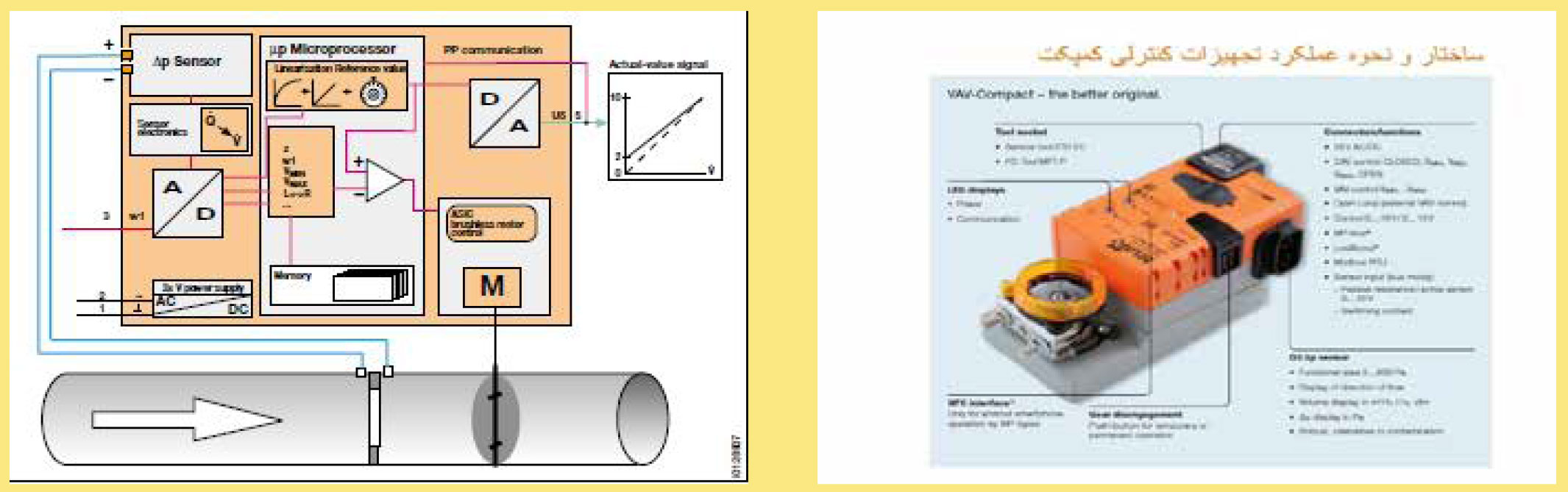
Compact controller consisting of a pressure difference measurement sensor, controller and actuator in one place
Note: Compact controller is currently used in Shahrokhi Industrial Group.
VAV damper control components
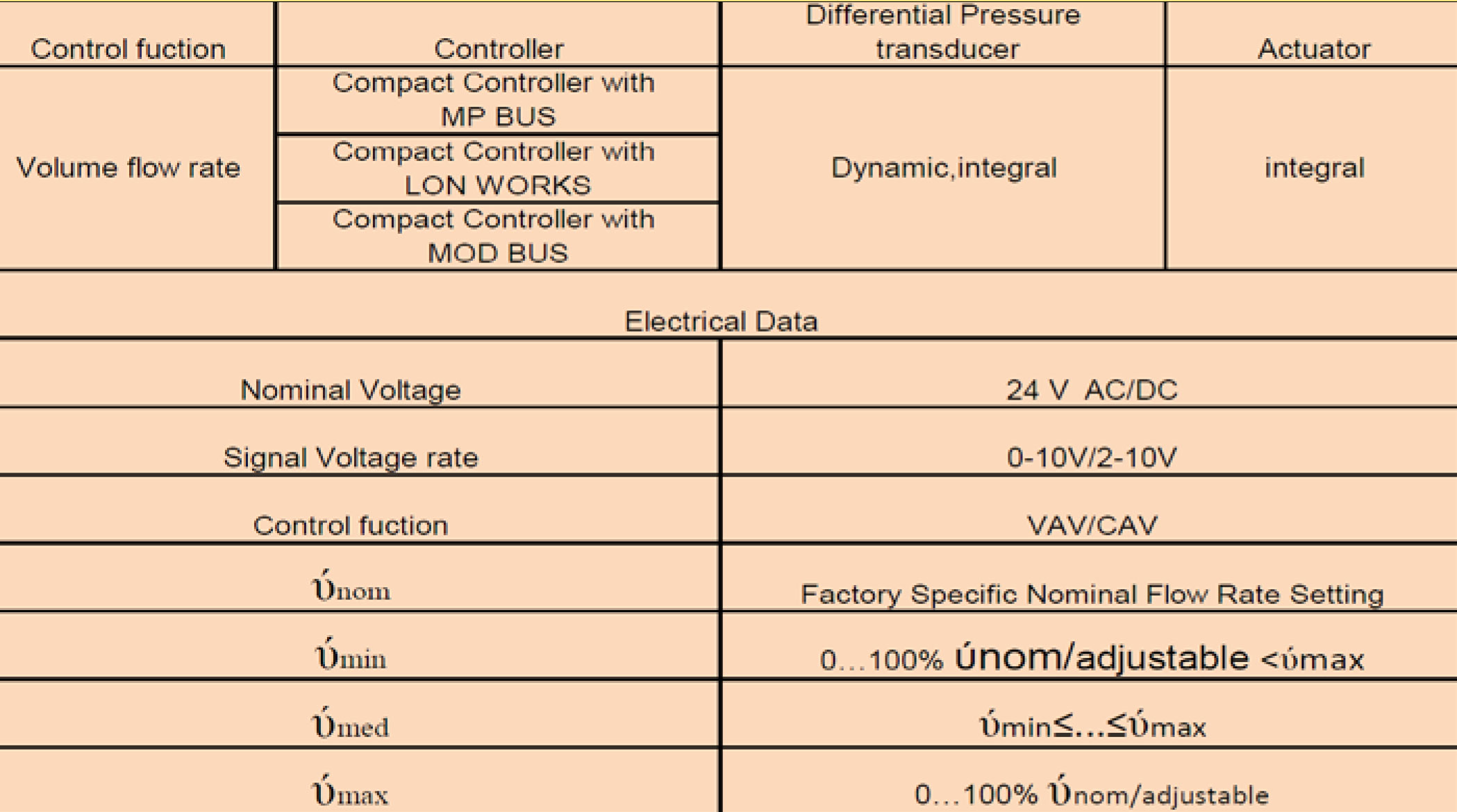
Table of technical specifications of the compact controller:
Table of technical specifications of compact controller
https://shahrokhimfg.com/wp-content/uploads/2023/02/vav-systems-en.jpg500500alandhttps://shahrokhimfg.com/wp-content/uploads/2026/05/shahrokhi-logo-site.webpaland2022-10-11 15:47:022023-02-12 12:56:42VAV Systems