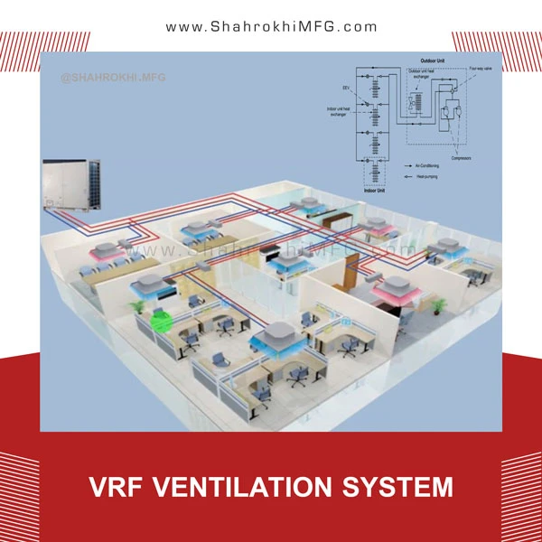
VRF ventilation system
Variable Refrigerant Flow (VRF) is a type of air conditioning technology that was invented in 1982 in Daikin, Japan. A VRF system, like splits, uses refrigerant for cooling and heating. This refrigerant is circulated in a circuit by an external unit between several internal units.
VRF systems are an advanced generation of ductless multisplit systems and one of the most efficient modern air conditioning systems, allowing more indoor units to be connected to each outdoor unit. VRF systems allow simultaneous heating and cooling as well as heat recovery to reduce energy consumption. Providing heating and cooling by a fully integrated system, with a single control system, no need for an engine room and maintenance technician, as well as low power consumption and a high coefficient of performance (COP) of the device, are some of the key advantages of these types of systems.
Also, other advantages of this system include the possibility of piping in long distances, the possibility of installation in high projects, the possibility of installing different types of indoor units, the central controller, and the use of R410a refrigerant, which is environmentally friendly, and also the lack of water consumption.
Condensation refrigeration cycle
The compression refrigeration cycle consists of 4 parts: condenser, evaporator, pressure relief valve and compressor. The compressor increases the pressure; The condenser transfers heat at a constant pressure and condenses the super heat steam and sends the high-pressure liquid to the pressure relief valve, which reduces the pressure during the constant entropy process, and the evaporator also takes the heat from the environment at a constant pressure and cools the environment. The important thing about this cycle is that by reversing the position of the condenser and evaporator, it becomes a heating cycle, which is called a heat pump.
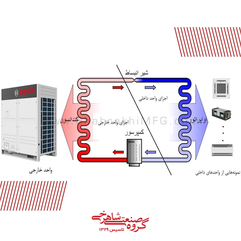
Showing the internal and external components of the VRF system in the refrigeration cycle
VRF variable refrigerant flow systems
Variable refrigerant flow systems are the same refrigeration cycle in which the refrigerant flow rate is changed by means of a variable speed compressor (inverter) in the outdoor unit and an electronic expansion valve (EEV) in the indoor unit to provide comfort conditions. This cycle is generally the same as the condensation refrigeration cycle, but it has a series of minor differences as follows:
In air conditioners, the internal unit only includes the evaporator, but the external unit includes a compressor, condenser and pressure relief valve, which makes it possible to have only 10 to 15 meters of piping between the internal and external units because the pressure drop process in the expansion valve and in The external unit occurs and a significant drop in capacity occurs as the piping becomes longer, and their compressor does not have enough capacity for this.
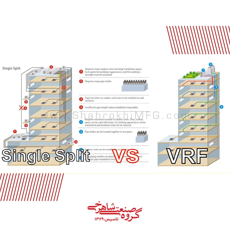
Comparison of VRF and single-spilt systems in a multi-story building
But in the VRF system, the internal unit includes the evaporator and pressure relief valve, and the external unit includes the condenser and compressor. This small change makes it possible to pipe up to 1 km in these systems, and we can have a pipe height of up to 110 meters, and the efficiency increases. Also, with the ability to connect 64 internal panels to each external unit, we can use them in high-rise buildings.
In these systems, the change of use from the heating system to the cooling system is done through a 4-way valve as shown in the figure below.
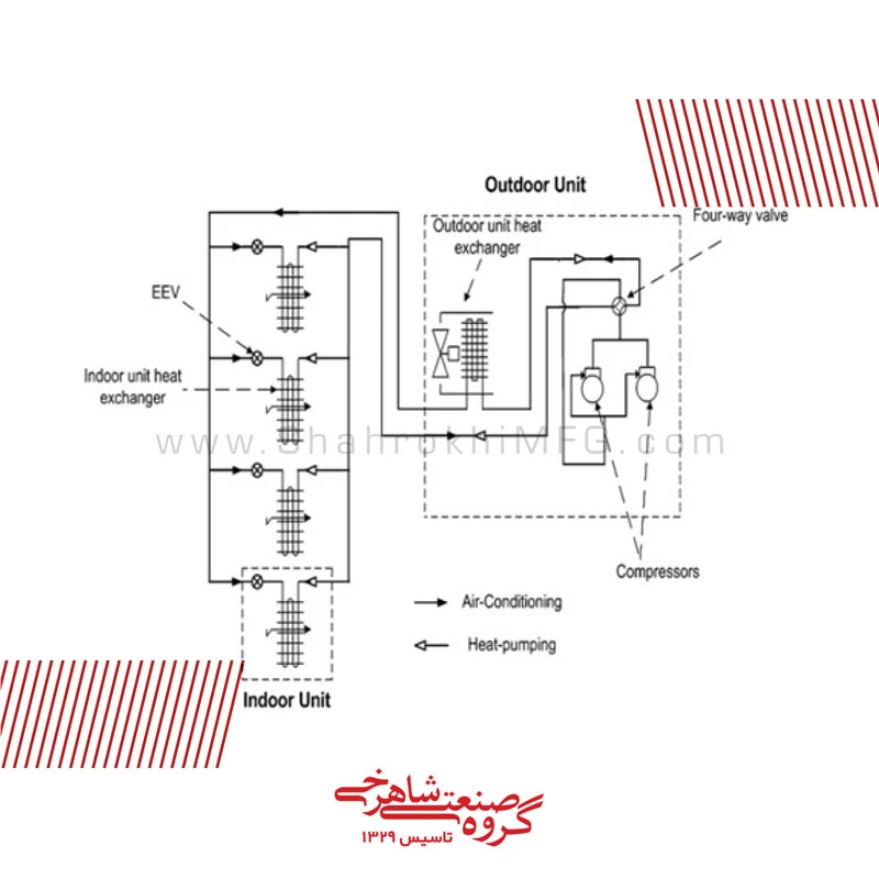
4-way valve performance and changing VRF system performance
This figure includes an external unit with two compressors and 4 internal units, in the cooling mode (solid arrows), the refrigerant is compressed in the compressor and is directed to the condenser (converter of the external unit) through the 4-way valve, and then enters the internal unit and There, it passes through the electronic expansion valve and enters the evaporator (converter of the indoor unit) and takes heat from the environment; But in the heating mode (empty arrows), after being compressed in the compressors, the 4-way valve enters the refrigerant into the internal unit, where it first enters the condenser (converter of the internal unit) and gives heat to the environment, then it expands in the expansion valve and The external unit enters and takes heat from the outside environment in the evaporator (converter of the external unit).
These systems also have a special feature in addition to cooling and heating which is the feature of all compression refrigeration cycles, which is the ability to simultaneously cool and heat in different spaces by means of a compressor. This feature is very useful for places like hospitals or places that have data centers and can provide up to 2 times the efficiency for the same capacity.
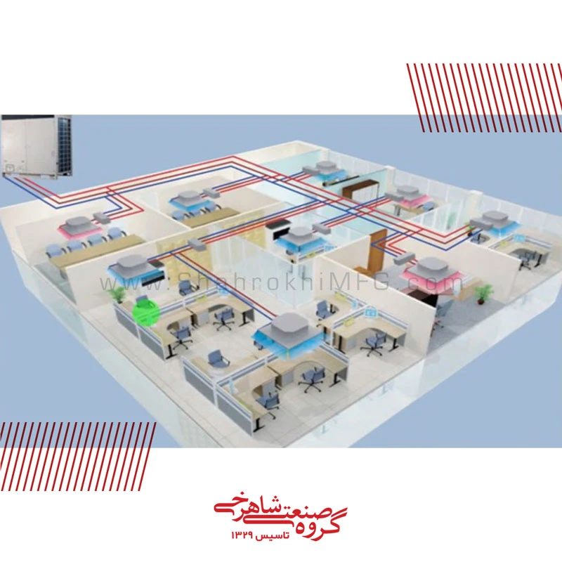
Simultaneous heating and cooling by a VRF unit in different zones of a building
This is done in such a way that part of the refrigerant after condensing in the compressor in the outdoor unit does not enter the condenser of this unit and instead of entering the condenser of the outdoor unit, it enters the indoor environment and in the indoor unit, the place that needs heating. It is entering the evaporator without passing through the expansion valve. In this case, the evaporator acts like a condenser, and the refrigerant comes out as a dense liquid and enters the internal units that are responsible for cooling through the pipes along with another part that was condensed in the condenser of the external unit.
The various components of these systems include:
External unit with a capacity between 7 and 26 kW as a front panel, from 25 to 50 kW as a single panel and from 50 to 200 kW as several external units that are modularized together. The internal components of this unit are as follows:
External unit components
- Compressors
- Fan (axial)
- Coils (condenser)
- Electronic board
- Inlet and outlet valves
- Accumulators (as a reserve source, in which the refrigerant is stored if necessary, and they also regulate the entry of gas into the compressor.)
- Sensors
- Oil separators
* The compressor of these systems is generally scroll and hermetic or semi-hermetic, which is almost unrepairable.
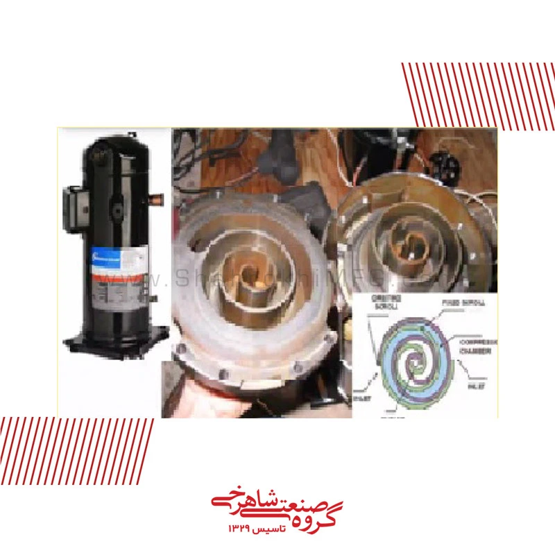
Internal and external view of scroll compressor
Indoor unit components
- Fan
- Expansion valve (after the inlet pipes)
- Coil (in the inlet pipe, which is generally smaller in diameter, the refrigerant enters as a liquid or a combination of liquid and gas, and after passing through the expansion valve, it leaves the outlet pipe (gas pipe) as a gas. The gas pipe is usually larger and if It’s cool to the touch.)
Copper pipes
In VRF systems, these pipes are the interface between indoor and outdoor units and all components in general. The important thing about branches is that there are branches that are responsible for the proper distribution of refrigerant, and if proper branches are not used, the distribution of refrigerant will not be proper and we will not have proper heating and cooling, or even a part of the system will be disturbed.

")

Leave a Reply
Want to join the discussion?Feel free to contribute!